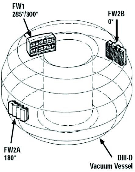
Fig. 1 Fast wave antenna locations on DIII–D.
Ports List | Back | Foward
ICH ant.
0 R-0
ICRF ANTENNA
High-power experiments with waves in the ion cyclotron range of frequencies
(ICRF) have been performed on the DIII-D tokamak since 1988. This is owing to
the excellent penetration of these waves to the core of a high density plasma and
to the efficient high-power sources that are available in this frequency range. The
DIII-D program has used ICRF heating systems from its inception, and has
developed the relevant technologies both to meet its own programmatic needs
and to contribute to the development of the next step ICRF system.
An ICRF system is composed of three main parts: an rf source, generally
constructed from a modified broadcast transmitter, transmission lines to convey
the power from the source to the tokamak, and a wave launcher (antenna)
mounted in the tokamak vacuum vessel. The transmission line includes
impedance matching and phase control elements because the launchers consist
of a phased array of inductive elements (antennas), whose input impedance is
quite different from the characteristic impedance of the transmission line.
The DIII–D vacuum vessel has three midplane locations for antennas, as shown
in Fig. 1. At 285°–300° the original four strap antenna, FW1, is located. This
antenna is designed for short pulses of 2 seconds and supports operating
frequencies of 30–60 MHz. At 0° and 180° are located two water-cooled four
strap antennas, FW2A, and FW2B, which are designed to operate at a higher
frequency range of 60–120 MHz, although as low as 30 MHz is possible with
some efficiency degradation.
A 2 MW 30–60 MHz, FW system has been in operation on DIII–D since late 1990
connected to FW1. This system has successfully demonstrated the technology of
a FW system, including the transmitter, transmission and matching network, and
antenna-plasma coupling in either the electron heating mode or the current drive
mode.
A 4 MW system was added in 1994 consisting of two systems each having its
own 30–120 MHz transmitter with output power of 2 MW over a frequency range
of 30 to 80 MHz, then decreasing linearly to 1.5 MW when the frequency reaches
120 MHz. Each transmitter is connected to a four strap antenna, FW2A or FW2B,
by an all ceramic insulated coaxial transmission line. The transmission line is
configured to provide the flexibility of adjusting the phasing of the straps for
electron heating (0,p,0,p) or for current drive (0,p/2,p,3p/2), while providing
matching between the antenna-plasma impedance (»1–5 ohm) and the 50 ohm
impedance that the transmitter requires for optimum power delivery. The
transmission system must also compensate for the mutual inductance between
the straps, which has been achieved by using a decoupler developed earlier for
the original 2 MW DIII–D FW system.
Fig. 1 Fast wave antenna locations on DIII–D.